Optical flash trigger with second pulse detection
 Ceska verze
Optical flash trigger with second pulse detection |
Ceska verze |
| Count | Value | Mark | |
Count | Value | Mark |
|---|---|---|---|---|---|---|
| 1 |
BPW42 |
3 | 33k | R5,R11,R13 | ||
| 1 |
4.7uF |
C1 |
2 | 1M |
R7,R15 | |
| 2 |
470nF |
C2,C4 |
1 | 10M | R8 | |
| 1 |
10uF |
C3 |
1 |
330 | R9 | |
| 2 |
100nF |
C5,C6 |
3 |
1k | R10,R14,R17 | |
| 3 |
1N4001 |
D1,D2,D4 |
1 |
4k7 |
R12 | |
| 1 |
LED1 |
D3 |
1 |
330k |
R16 | |
| 3 |
BC547B |
Q1,Q4,Q5 |
2 |
TIC106D | SCR1,SCR2 | |
| 1 |
BC517 |
Q2 |
1 |
78L05 | U1 | |
| 1 |
2k2 |
R1 |
1 |
74HC74 | U2 | |
| 1 |
680 |
R2 |
1 |
button |
S1 |
|
| 1 |
100 |
R3 |
1 |
switch |
ETTL |
|
| 2 |
100k |
R4,R6 |
| Stabilized power source. Working point of Q4 must be set with relatively high accuracy. Therefore, stabilized power source (7805 in my case) is needed. The total power consumption of the trigger is relatively low and 7805 does not need any cooling. Even the cheaper TO220 package can be used. To achieve higher sensitivity, optical sensor is driven by full voltage (9V in my case). If your power source is not stable enough then the optical sensor can be also connected to stabilized +5V. Sensitivity will be slightly smaller but it should not be real problem. |
| Optical sensor. Phototransistor
BPW42 is
used here to detect light pulse. After filtering by R11, C2 and R13
only rapid changes of lighting are sent to amplifier. The optical
sensor must be located so that it can be reached by light from your
master flash.
Fortunately, due to very good sensitivity, the sensor does not have to
"see" your master flash directly. Light reflected from walls is
sufficient.
In my case I just made a hole into plastic box with the trigger and put
the sensor to this hole - this was enough. Phototransistor BPW42 is sensitive also to infrared light. Therefore, IR filter can be used over the on-camera master flash. This way, the on-camera flash can be completely filtered out from your images. The cheapest IR filter is an unexposed but developed slide film (e.g. black leading part). |
| Amplifier. The pulse from
phototransistor is amplified by Q4. The base voltage (working
point) is set so that even very small pulse (just 50mV) will open the
transistor. Transistor Q5 just inverts pulse from negative back to
positive.
Sensitivity of this combination sensor/amplifier is so high that the
trigger can be located even in a different room and it will still fire.
|
| Second pulse detector.
This circuit will detect second pulse for Canon ETTL and for digital
cameras. IC 7474 is used with self-reset after approximately 1 second
(R4
R6 C3). Therefore, you don't have to worry about synchronization. The
auto-reset is needed because the trigger is very sensitive and it can
sometimes incorrectly react also to other events like switching light
on (especially fluorescent lights). Also, some minimum time between the pulses is needed (R5 C4). It set to approximately 10ms - this should avoid problems with "shape" of the first measuring pulse (it can sometimes consist of many very small pulses). Just for information, the delay between the first measuring and the second main pulse for Canon EOS300/30 is 65 and 75ms. Olympus C4000Z has 100ms between pulses. If you don't have neither Canon EOS camera with SpeedLite flash nor digital camera, the second-pulse detector can be completely removed. |
| Switches. S1 is used for firing your flashes manually. This way, you can check if all flashes are firing correctly. ETTL switch can be used to switch between first/second pulse detection. When the switch is in upper level then flashes are fired immediately after the first pulse (usually used with built-in flash of your analog camera). When the switch is in lower level then the trigger waits for the second pulse (when you use system flash with E-TTL or if you have a digital camera). You can use a dual switch here and add a LED diode for indication if you are in ETTL mode. |
| Thyristor array.
Ground of all
flashes was connected together. The positive pin was connected to a
thyristor. The 400V/3A thyristors used here should survive just
any flash. In my particular case, 8 thyristors were used. This way I
could simulate variable flash power (I used two soft boxes with two
flashes each and this allowed me to use 0/50/100% of power). The
remaining thyristors can be used for fill, background, hair light.... The scheme here uses just one resistor R2 common to all thyristors. If the thyristors are not exactly the same then some of them may not fire. In this case it would be better to have separate resistor for each thyristor. 4k7 should be a good value here (not tested). |
| Flash confirmation.
After I used the
device for a while I found that I want to know if the flashes fired.
The problem was that when I looked through viewfinder of my SLR I did
not see the flash due to mirror black-out. Usually, there was no
problem as the trigger is very sensitive but anyway I wanted to be able
to check if the flashes fired. The C1, R7 and R8 combination together
with
very high Beta of Q2 ensure that LED1 is lighting for 5-15 seconds
after flash. |
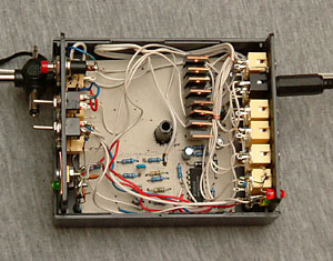
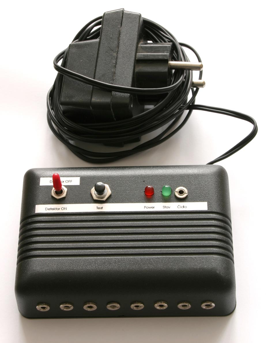
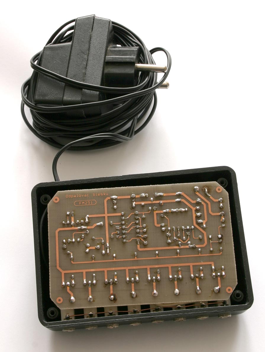
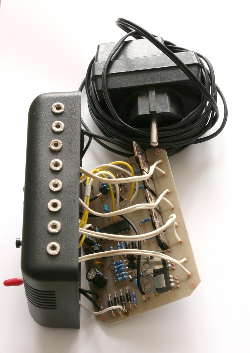
The trigger was built into a plastic case. Mono 3.5mm jacks were used for flash connection. I had no simple way how to make a real printed circuit and therefore "paper circuit" was used :-). I just drew the components on hard paper, made holes and connected the pins on the opposite side.
The box on these pictures has many connectors because it was used also for lighting objects with RGB LED (mosquito crystal).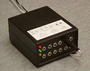 |
 |
 direct flash - hard shadow, dark
background
|
 direct flash + bounce from
ceiling
|
 flat light and hard shadows from on-camera flash |
 several flashes, softbox |
Several flash triggers have been already built based on this description. I have got slightly modified version of the trigger together with PCB from Zdenek Maly. Because he had problem with obtaining phototransistor BPW42, it was replaced by photodiode 1PP75. Optical senzor is in this case external - the advantage is possibility to attach the cable direcly to camera.
|
|
|
|
|
|
|